Good crawl space dehumidifier placement gives the machine a clear air path, a dependable drainage route, and enough space for inspection and service. The middle of the crawl space is not automatically the right position. A slightly off-center location may work better when it avoids obstructions, reaches a suitable drain, and allows air to move between the areas that need control.
This guide helps you evaluate a proposed position before equipment is installed. It applies the same planning questions to compact gravity machines, integrated-pump units, and permanent systems, while leaving model-specific clearances and installation requirements to the matching manufacturer manual. See our crawl-space dehumidifier hub for the equipment and monitoring guides.
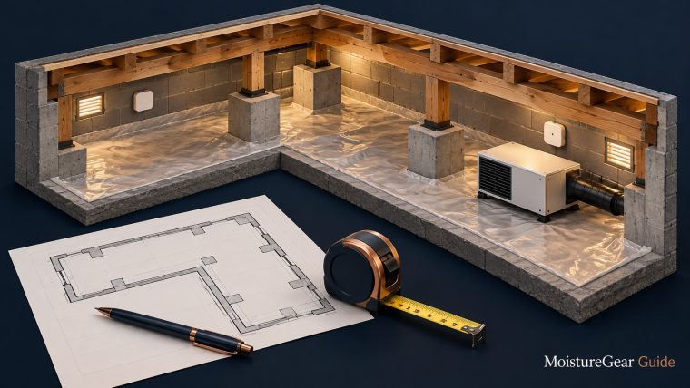
Begin with a sketch of the space
Draw the crawl-space sections, access opening, foundation piers, low beams, major ducts, plumbing, electrical outlets, and likely drain destination. The sketch does not need architectural accuracy, but the distances and narrow points should be real measurements rather than guesses.
Mark the areas that show persistent dampness or have higher humidity readings. Keep those observations separate from the proposed equipment position. A humid corner may be the result of poor circulation or water entry, and placing the machine beside it does not establish which explanation is correct.
PNNL’s crawl-space inspection guidance identifies water, liner, duct, and structural issues worth documenting. If inspection reveals standing water, exposed electrical connections, or other unsafe conditions, arrange professional help instead of continuing an equipment-placement exercise in the affected area.
Use the sketch to propose two or three practical locations. Comparing alternatives makes the tradeoffs visible before the drain line and supports commit you to one position.
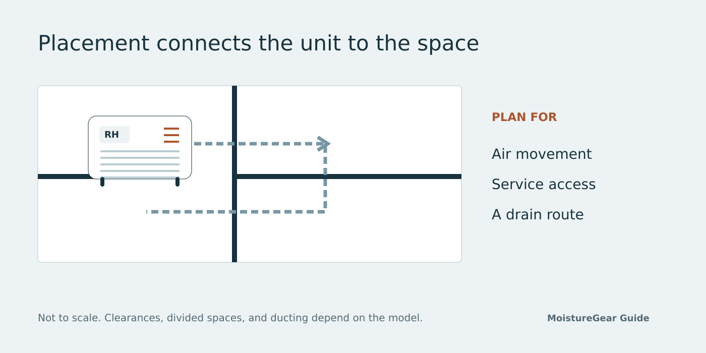
What a usable position must provide
| Requirement | Question to answer at the proposed location |
|---|---|
| Air intake | Can air reach the inlet without a wall, liner, or stored item obstructing it? |
| Dry-air discharge | Can the outlet send air into the intended space instead of a nearby obstacle? |
| Distribution | Can the air circulate to separate bays or follow an approved duct plan? |
| Drainage | Does the entire outlet route satisfy the unit and pump instructions? |
| Stable support | Can the machine remain in its required operating orientation? |
| Electrical supply | Is a suitable outlet reachable without improvised wiring or adapters? |
| Routine maintenance | Can the filter and drain connections be accessed safely? |
| Removal | Can the equipment be brought out for authorized service? |
A location that fails one of these tests needs revision even if it appears convenient on the sketch. The point is to choose a place where the complete system can function, not merely where the cabinet can sit.
Do not choose the center without checking airflow
A central open position can be sensible in an uncomplicated crawl space, but the geometry matters. Foundation walls, piers, ducts, and changes in floor elevation can interrupt air movement. A visually central machine may serve only the easiest nearby air path.
Identify the inlet and discharge direction on the specific unit. Some cabinets move air through opposite ends, while other equipment uses different arrangements. A generic diagram of a dehumidifier is not enough to tell you which side should face the open part of your crawl space.
Keep the discharge from immediately recirculating into the inlet through a short path where possible within the approved layout. The useful objective is air exchange with the space being controlled. If a distant bay remains humid while the equipment area is dry, the position or distribution plan deserves attention.
ENERGY STAR’s placement guidance emphasizes unobstructed circulation. For crawl-space equipment, follow that principle through the exact manufacturer clearances rather than applying a universal distance to every cabinet.
Check the drain before settling the location
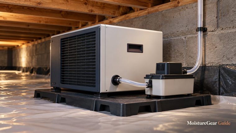
For gravity drainage, the cabinet outlet and downstream route need the configuration specified in the manual. The closest drain may not be the best one if reaching it involves a rise, an unsuitable connection, or a hose that is difficult to inspect.
Measure the elevation changes along the route. Do not assume that water will pass correctly through a hose merely because its final destination is lower than the unit. An obstruction between those points can change the decision. Supports or a different location may help only when the whole route remains valid.
For pumped drainage, verify lift, tubing requirements, route length, and termination against the specific appliance or pump documentation. An integrated pump expands the practical location options, but it does not remove all limits or make the destination irrelevant.
Our gravity-drain versus pump guide explains these differences, while the pumped crawl-space shortlist compares equipment approaches. Resolve the drainage arrangement before locating the cabinet where moving it later would be difficult.
Make support and elevation part of the plan
The required operating orientation and leveling instructions come from the matching manual. A stable support arrangement should keep the cabinet correctly positioned and preserve access to its drain and service points. Uneven blocks or an improvised shelf are poor substitutes for a considered support plan.
Raising a gravity-draining appliance can improve the outlet relationship to its drain, but the support height uses overhead clearance. Include it in the installed dimensions. Our low-profile equipment guide explains why cabinet height and complete installation height differ.
If suspension is appropriate, use equipment intended for the model and a suitable structural attachment assessed by someone qualified. Do not hang a unit from its sheet-metal casing, miscellaneous straps, or an unverified part of the building. The appliance manual and kit instructions should agree with the proposed arrangement.
Elevation is not protection against every flood condition. A crawl space with water-entry risks needs the water problem addressed. Positioning an electrical appliance above an assumed puddle level does not replace that work.
Leave space to work on the machine
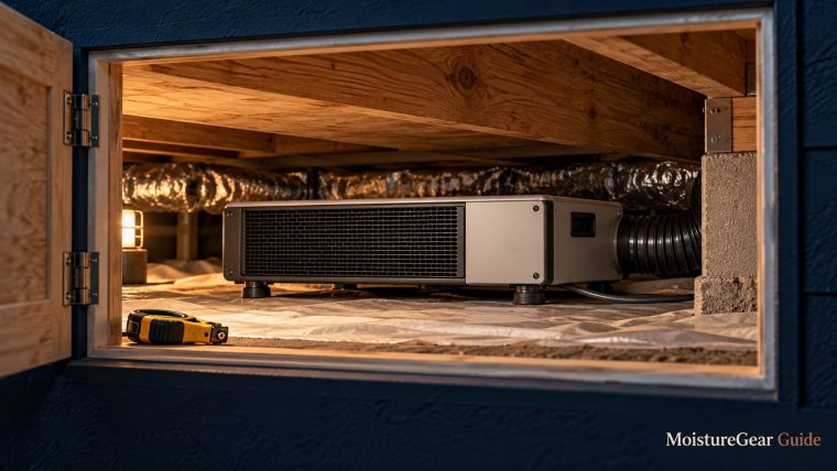
Find out where the filter comes out, where the electrical connection is reached, and which panels an authorized technician needs to access. Routine maintenance clearance and full repair clearance may differ. A cabinet can have enough room for airflow yet remain impossible to service comfortably.
Santa Fe’s Compact70 installation literature, for example, distinguishes service access, filter access, and airflow considerations. Current-generation equipment must follow its own manual, but the example shows why a single clearance number is incomplete.
Preserve a practical approach from the hatch. A hose crossing the only route or a unit blocking access to plumbing can create problems beyond dehumidifier maintenance. Place tubing and cords according to their instructions while maintaining safe access for other work under the home.
Think through removal now. If the appliance eventually needs bench service, a technician should have a plausible way to disconnect and extract it. Easy access is an ownership feature even though it rarely appears near the top of a product listing.
Keep the equipment away from unsuitable conditions
Choose a position protected from the water exposure, contaminants, and other conditions excluded by the appliance instructions. A crawl-space unit is not necessarily outdoor equipment, and a robust-looking cabinet does not make it appropriate for contact with floodwater or an active leak.
Identify plumbing joints or drains above the planned position that have shown leakage. A different location may reduce exposure, but the leaking component still needs repair. Similarly, avoid placing the unit where loose insulation, dust, or damaged liner material can obstruct its inlet.
Do not use the machine as a step, storage shelf, or support for unrelated items. Keep enough clear working area that a person can inspect it without leaning on the cabinet or disturbing the water outlet.
The EPA’s moisture guidance treats source reduction as part of moisture control. A suitable equipment position works within that plan; it should not become a way to overlook a leak because the nearby humidity reading improves.
Place the humidity sensor to represent the area you want controlled
A built-in sensor observes air at the location and through the control behavior specified by the manufacturer. It does not directly measure every corner of the crawl space. That limitation matters when the layout is divided or the dry-air outlet affects the immediate surroundings.
Use an independent monitor away from the discharge stream to evaluate the controlled environment. Avoid setting it against a wet surface or directly beside an opening that samples outdoor air. Allow stabilization as its instructions require, and record temperature along with RH.
A compatible external humidistat may be useful where the appliance is in a less representative position, but compatibility and wiring must be confirmed. Do not assume any remote controller or Wi-Fi sensor can command any dehumidifier. A monitoring device and an equipment control are different products.
Our crawl-space humidity guide discusses interpretation, and the Wi-Fi monitoring guide covers remote observation. Place the sensor deliberately rather than expecting the appliance display to prove that the whole area is controlled.
When separate sections need an air-distribution plan
A crawl space with a partial foundation wall, a narrow connecting opening, or dense ductwork may need more thought than a standalone placement diagram suggests. Document those barriers and compare readings on both sides during normal operation.

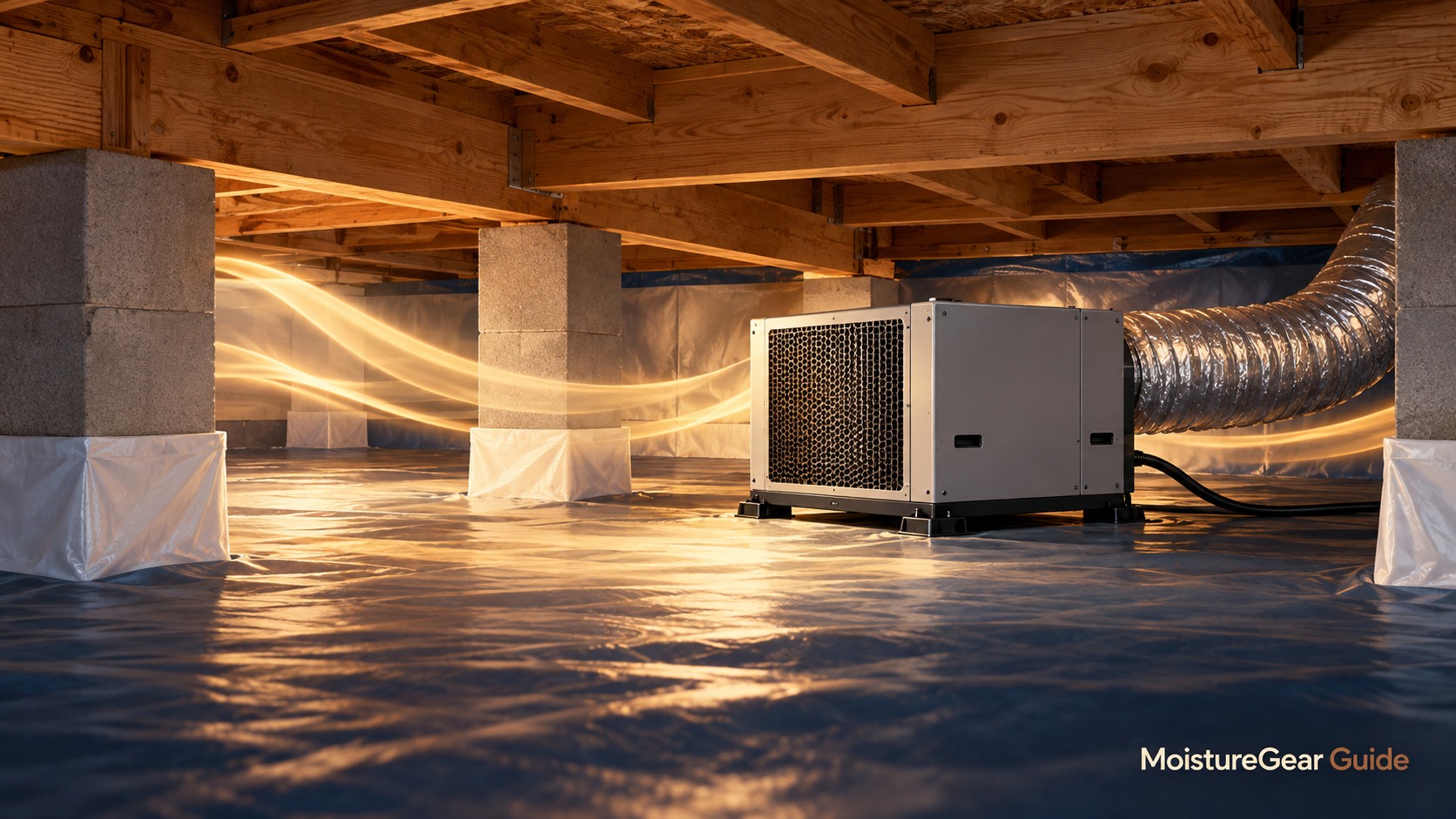
Ductable HDi90 configuration pictured; it is distinct from a pump-only cabinet without the required ducting parts.
If duct accessories are proposed, verify that the exact model supports the configuration. The equipment’s allowable external static pressure, duct sizes, route, and controls matter. A product-family image with a collar is not proof that every variant can accept the planned ducting.
AlorAir separately describes its built-in-pump HDi90 and ductable relatives. That distinction illustrates why the SKU and supplied parts must be checked before designing the air path.
A qualified installer can assess whether relocation, approved ducting, or separately controlled zones make sense. Do not cut openings through structural foundation components or add long duct runs casually. The goal is a deliberate path for air, with performance checked at the locations the system is intended to serve.
Placement and sizing need to agree
A physically convenient location can restrict the airflow or equipment options enough to affect the system decision. Conversely, a correctly rated machine may be awkward to install at the only available drain. Keep these constraints in the same assessment.
Record the temperature where the inlet will draw air. A warmer nearby equipment area is not necessarily representative of a cooler far bay. Minimum operating temperature and rated extraction under a laboratory condition are not identical requirements.
Our crawl-space sizing guide explains how source conditions, enclosure, and layout influence equipment choice. If the proposed position would require a much smaller cabinet, verify that the reduced equipment choice can still meet the assessed need.
Do not buy extra capacity as a workaround for blocked airflow. If the appliance repeatedly processes nearby dry air while a separate bay remains humid, improving distribution may matter more than raising the pint rating.
Compare these three possible positions
Close to the access opening: This can simplify maintenance and removal. It may be a good choice if the air path is open and the drain can be arranged correctly. It is less useful if the hatch position leaves the machine beside an outdoor opening or isolated from the rest of the space.
Near the suitable drain: This can shorten a gravity route and make drain inspection easier. Check whether the location also provides circulation and working room. Drain convenience alone should not place the inlet behind a pier or beneath a leaking pipe.
Within the largest open section: This can favor air movement, but it may create a longer water route and a more difficult service approach. A pumped arrangement or approved duct plan might change the tradeoff, provided the resulting system follows its documentation.
These are alternatives to evaluate, not a ranking. Mark the gains and compromises for each on your sketch, then ask the installer to explain why the final position satisfies all the important requirements.
Check the result in more than one location
After proper startup, keep the initial setting steady long enough to observe a useful trend. Follow the manufacturer’s startup and control instructions rather than repeatedly resetting the unit because the display fluctuates.
Compare the equipment area with at least one distant or separated section. A large, sustained difference deserves investigation into airflow, incoming moisture, sensor placement, and temperature. A small disagreement between two sensors does not automatically prove a placement fault.
Inspect the water route while the machine operates through its normal procedure. Look for accessible leaks, unintended hose movement, or a termination that no longer stays clear. Do not open housings or reach around energized components to create a test.
Record the location and configuration once the system works as intended. Photographs of the supports, filter side, drain, and control setup are useful for future maintenance or support calls.
Follow up after weather and maintenance changes
A good first-day reading is only one observation. Check the arrangement after representative rainfall, seasonal temperature changes, and any work performed in the crawl space. A hose can be displaced during plumbing work, and a new storage item can obstruct an air path.
When cleaning or replacing the filter, recheck the nearby drain and accessible support. Follow the approved maintenance procedure and restore the equipment to the documented configuration. Our crawl-space cleaning guide keeps those tasks within the appropriate user scope.
If conditions change sharply, revisit the system rather than assuming the setpoint needs to be lowered. The change may come from water entry, a damaged vapor barrier, a drain fault, or a disconnected duct. The original sketch and sensor log make that investigation more focused.
The best position is one that remains workable during ownership: air reaches the equipment, water reaches the intended destination, people can inspect the installation, and measurements show that the intended crawl-space sections are being controlled.
Selected sources
- ENERGY STAR: Dehumidifier placement and buying guidance
- PNNL: Look at the crawl space for moisture issues
- Santa Fe Compact70 installation literature
- EPA: Mold, moisture, and your home
- AlorAir Sentinel HDi90 manufacturer page

About the author
Davis Murphy
Davis Murphy writes about dehumidifiers, indoor humidity, and home moisture control at MoistureGear Guide. His articles explain how to compare equipment, understand capacity ratings, and plan for drainage and maintenance. He focuses on clear, practical guidance to help readers choose a dehumidifier suited to their space and needs.